H91 SERIES
Application Notes for
RF Switches
|
SPECIAL ORDER PRODUCT
- CONSULT FACTORY BEFORE ORDERING -
|
|
|
|
|
|
|
- Replaceable SMA Connectors
- Low Profile: 0.24" thickness with integrated TTL- compatible driver
- High Speed
- High Isolation
- Low VSWR, Low Insertion Loss
- Nonreflective and Reflective Models
|
|
|
The H91 Series consist of a family of high-speed and high-isolation hermetically sealed switches with integrated drivers that operate over the frequency range from 1 to 18 GHz.
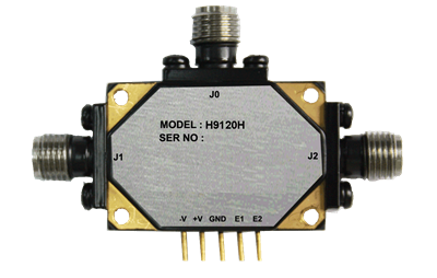
The H91 Series switches are equipped with removable SMA female RF connectors permitting field replaceability or integration as drop-in modules. Package area and volume are minimized and overall thickness, with the built-in driver, is only 0.24”.
The H91 family consists of SPDT and SP4T switches in both reflective and non-reflective configurations.
On all switches, the dc and control ports are located in line on one wall of the module above the RF connection level. This makes the switches ideally suitable for printed-circuit type mounting.
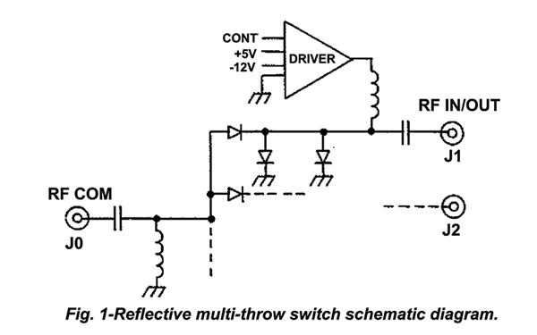
REFLECTIVE MULTI-THROW SWITCHES
All models in this group use an integrated assembly of PIN diodes mounted in a microstrip transmission line in a series-shunt arrangement as shown in Fig.1.
When positive current is applied by the driver, the associated port is Off since the corresponding shunt diodes are biased to a low resistance and the series diode to a high resistance. With negative current, the converse conditions are established and the port is ON.
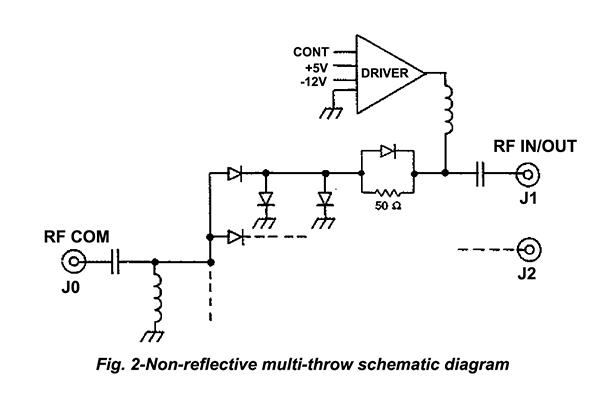
NON REFLECTIVE MULTI-THROW SWITCHES
The circuit arrangements for this series is shown in Figure 2.
When positive current is applied the port is turned OFF. All the series diodes in that port are reverse-biased and the impedance at the output of the port is then effectively that of the 50-ohm resistor.
SWITCHING SPEED
All models exhibit transition times of less than 10 nanoseconds between 10% to 90% and 90% to 10% of the RF power.
ON time, the time from 50% point of the TTL command to the 90% level of the detected RF, is less than 25 nanoseconds for all models; OFF time, from the 50% point of the TTL command to the 10% level of the detected RF, is less than 20 nanoseconds.
HERMETIC SEALING
All switches are housed in enclosures using sealed glass-to-metal “feedthru” connectors for true hermeticity.
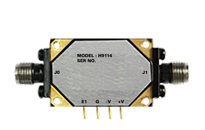
Model H9114 Hermetically Sealed SPST Switch
| MODEL NO. |
CHARACTERISTIC |
FREQUENCY (GHz) |
| 1.0 - 2.0 |
2.0 - 4.0 |
4.0 - 8.0 |
8.0 - 12.4
|
12.4 - 18.0 |
| H9114 |
Min Isolation (dB) |
60 |
74 |
80 |
80 |
80 |
| Max Insertion Loss (dB) |
0.9 |
0.9 |
1.2 |
1.6 |
2.5 |
| Max VSWR (On position) |
1.4 |
1.4 |
1.75 |
1.75 |
2.0 |
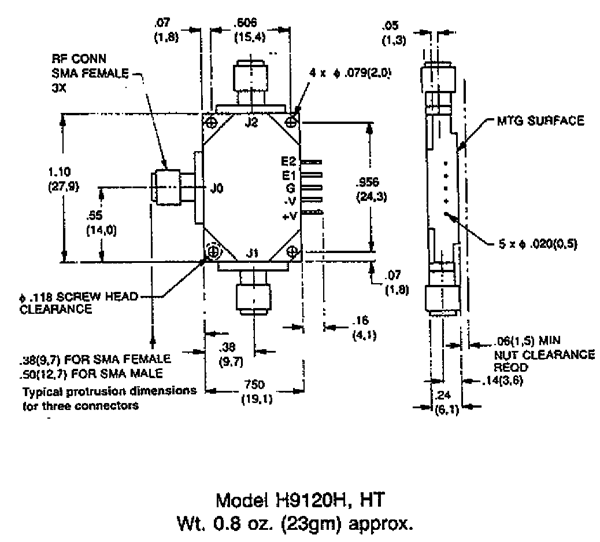
Models H9120H and H9120HT Hermetically Sealed SPDT Switches
| |
FREQUENCY (GHz) |
| MODEL NO. |
CHARACTERISTIC |
1—4 |
4—8 |
8—12.4 |
12.4—18 |
| H9120H |
Min. Isolation (dB)
Max Insertion Loss (dB).
Max VSWR (ON)
|
60
1.1
1.75 |
60
1.4
1.75 |
60
2.0
1.75 |
50
2.5
2.0 |
| H9120HT |
Min. Isolation (dB)
Max Insertion Loss (dB)
Max VSWR ON
Max VSWR Port OFF
|
60
1.3
1.75
1.75 |
60
1.7
1.9
2.0 |
60
2.5
2.0
2.2 |
50
3.0
2.0
2.3 |
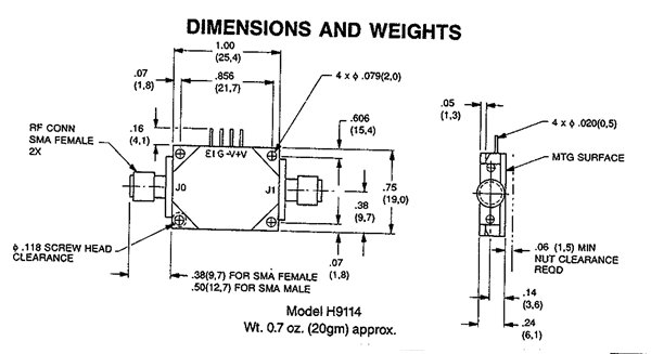
DIMENSIONS AND WEIGHTS
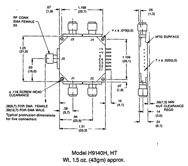
Models H9140H and H9140HT Hermetically Sealed SP4T Switches
 |
|
|
|
|
|
| |
FREQUENCY (GHz) |
| MODEL NO. |
CHARACTERISTIC |
1—4 |
4—8 |
8—12.4 |
12.4—18 |
| H9140H |
Min Isolation (dB)
Max Insertion Loss (dB)
Max VSWR (ON)
|
60
1.4
1.75 |
60
1.5
1.75 |
60
2.0
1.75 |
50
2.8
2.0 |
| H9140HT |
Min Isolation (dB)
Max Insertion Loss (dB)
Max VSWR On
Max VSWR Port Off
|
60
1.6
1.75
1.75 |
60
1.8
1.9
2.0 |
60
2.5
2.0
2.2 |
50
3.3
2.0
2.3 |
DIMENSIONS AND WEIGHTS
PERFORMANCE CHARACTERISTICS
| POWER HANDLING CAPABILITY |
|
Without Performance Degradation
|
| All Reflective Switches ...............1W cw or peak |
| All Non Reflective Switches |
| Input to any "OFF" port: 100 mW cw or peak |
| Input to any "ON" port: 1W cw or peak |
| Input to common port: 1W cw or peak |
SURVIVAL POWER
|
| Model H9114 2W average, 75W peak (1 µsec max. pulse width) |
| Reflective Switches.....1W average, 75W peak (1 µsec max. pulse width) |
| None Reflective Switches |
| Input to any "OFF" port: 1W average, 10W peak (1 µsec max. pulse width) |
| Input to any "ON" port: 1W average, 75W peak (1 µsec max. pulse width) |
| Input to common port: 1W average, 75W peak (1 µsec max. pulse width) |
| |
| SWITCHING SPEED (ALL MODELS) |
|
| Rise time.................................................... |
10 ns max. |
| Fall time....................................................... |
10 ns max. |
| ON time........................................................ |
25 ns max. |
| OFF time...................................................... |
20 ns max. |
| |
|
POWER SUPPLY REQUIREMENTS
|
| For one Port on |
| MODEL |
+5V ±5% |
-12 to -15V |
| H9114 |
65 mA |
20 mA |
| H9120H |
60 mA |
50 mA |
| H9120HT |
80 mA |
50 mA |
| H9140H |
95 mA |
60 mA |
| H9140HT |
135 mA |
60 mA |
| |
|
|
| CONTROL CHARACTERISTICS |
Control Input Impedance.......................
|
TTL, advanced Schottky, one unit load. (A unit load is 0.6 mA sink current and 20 µA source current.) |
Control Logic.........................................
|
Logic "0" (-0.3 to +0.8V) for port ON
logic "1" (+2.0 to +5.0V) for port OFF.
|
Dimensions in mm (Inches) Tolerances, unless otherwise indicated: .XX ±.02; .XXX ±.005 |
| |
|
|
| |
|
|
|
| ENVIRONMENTAL RATINGS |
| Temperature Range |
| Operating....................... |
-54°C to +110°C |
| |
| AVAILABLE OPTIONS |
|
Option No.
|
Description |
|
7
|
SMA male RF connectors |
| 9 |
Inverse control logic: "0" for port OFF and logic "1" for port ON. |
|
41*
|
Internal video filter, common port only |
|
42*
|
Internal video filter, output ports only |
|
43*
|
Internal video filter, all ports |
|
55*
|
Frequency range 0.5 to 18 GHz. |
| 64A |
SMB male bias/control connectors |
| | |
|
|
|
|
*See Application Notes for impact of this Option on specifications.
|
|
|