Kratos Microwave Israel

Full Line Product Catalog

Series F892 High-Speed Octave-Band SP2T Switches

Application Notes for RF Switches

SERIES F892

Series F892 high speed switches with integrated drivers are low-cost units that have been engineered to meet the need of microwave system designers for fast switching devices in small packages.

2 to 18 GHz Frequency Range

Frequency coverage from 2 to 18 GHz is provided by the three models in the Series: Model F8922 (2-4 GHz), Model F8924 (4-8 GHz) and Model F8928 (8-18 GHz). Each model is capable of extended bandwidth operation, typically 3:1, with only moderate degradation in performance at the band edges, as shown in the specifications below.

Fast Switching Shunt Design

All models are optimally designed, with respect to their size, for low VSWR and Insertion loss. As shown in the schematic below, a pure shunt design is used for the most practical realization of fast switching action. Although the use of a pure shunt mode imposes certain bandwidth limitations, frequency coverage in excess of octave bands has been maintained.
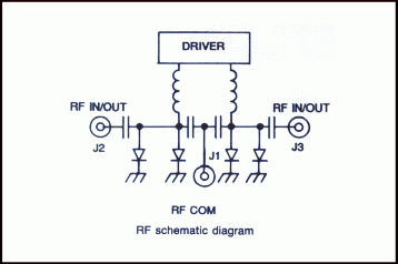
Series F892 Octave Band Switch RF schematic diagram 

The proper currents required to switch ports ON or OFF are provided by the integrated drivers which are controlled by external logic signals.

  • Low Cost
  • S, C and X-U band models
  • 10 nsec rise and fall times
  • Up to 60 dB isolation
  • As low as 1.0 dB Insertion loss
Model F8928 High-Speed Octave Band SP2T Switch

Model F8922 High-Speed Octave Band SP2T Switch


        THE TWO UNITS IN THIS
            SERIES ARE EQUIPPED
       WITH INTEGRATED DRIVERS

PERFORMANCE CHARACTERISTICS

MODEL
NO.
FREQUENCY
RANGE
(GHz)
INSERTION
LOSS MAX,
(dB)
ISOLATION
MIN,
(dB)
VSWR
MAX,
(ON)
F8922* 2-4 1.0 60 1.5
1.5-4.5 2.0 55 2.0
F8924* 4-8 1.4 50 1.5
3-9 2.3 45 2.2
F8928 8-18 2.3 45(1) 2.2
6-18 2.5 45(1) 2.5

*Special-order product. Consult factory before ordering. 

Switching Characteristics
   Rise Time............................................. 10 nsec max.
   Fall Time.............................................. 10 nsec max.
   ON Time............................................... 35 nsec max.
   OFF Time............................................. 30 nsec max.
   Repetition rate..................................... 10 MHz max.
Power Handling Capability
   Without Performance Degradation...... 2W cw or peak (2)
   Survival Power...................................... 2W average, 75W peak
(1 µsec max. pulse width)
Control Characteristics
   Control Input Impedance..................... Schottky TTL, one-unit load.
(A unit load is 2.0 mA sink current and 50 µA source current.)
Control Logic ......................................... Logic "0" (-0.3 to +0.8V) for port ON 
Logic "1" (+2.0 to +5.0V) for port OFF
Power Supply Requirements
   (For one port ON)................................. +5V ±5%, 65 mA
-12 to -15V(2), 20 mA
OPTION (G09) ENVIRONMENTAL RATINGS
Operating Temperature Range................ -54°C to +110°C
Non-Operating Temperature Range ...... -65°C to + 125°C
Humidity .................................................. MIL-STD-202F, Method 103B, Cond. B (96 hrs. at 95%)
Shock ...................................................... MIL-STD-202F, Method 213B,
Cond. B (75G, 6 msec)
Vibration ................................................. MIL-STD-202F, Method 204D, Cond. B (.06" double amplitude or 15G, whichever is less)
Altitude ................................................... MIL-STD-202F, Method 105C,
Cond. B (50,000 ft.)
Temp. Cycling .......................................... MIL-STD-202F, Method 107D,
Cond. A, 5 cycles
AVAILABLE OPTIONS
Option No.
Description
3
SMA female control connectors
7
SMA male RF connectors
7A
J1 SMA male; J2 and J3 SMA female
7B
J1 SMA female; J2 and J3 SMA male
9
Inverse control logic; logic "0" for port OFF and logic "1" for port ON
27
Single-port toggle control;
logic "0" connects J1 to J2
62
±15V operation
64
SMC male control connectors
64A
SMB male control connectors
65
±12V operation
G09 Guaranteed to meet Environmental
Ratings
G12 RoHS Compliant
 G18 REACH Compliant


NOTES

(1) Isolation 40 dB above 16 GHz.
(2) With -15V power supply. Reduces to 1.5W with -12V power supply. Units may be operated at higher input power levels some increase in switching time when -30V power supply is used (consult factory for this option). 

DIMENSIONS AND WEIGHTS

Dimensions and Weights for Model F8922 Octave Band Switch Dimensions and Weights for Model F8924 Octave Band Switch
Dimensions and Weights for Model F8928 Octave Band Switch
Dimensions in  mm (Inches) Tolerances, unless otherwise indicated: .XX ±.02; .XXX ±.005  


The information contained in this data sheet is basic marketing information and does not contain any export controlled information.